
Finned Tube Heat Transfer Principle
The heat transfer principle of finned tube mainly includes two mechanisms: heat conduction and convection heat transfer.
When the hot fluid flows through the finned tube, the heat is first transferred from the fluid to the base tube of the finned tube by heat conduction.
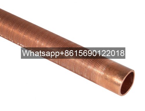
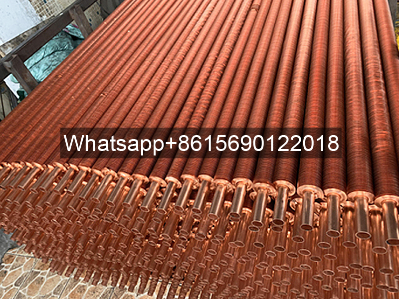
Heat conduction is the process of heat transfer from a high-temperature object to a low-temperature object, which mainly depends on the microscopic molecular movement of the substance. In the finned tube, the base tube material is usually a metal with good thermal conductivity, such as copper, aluminum, etc., which can quickly transfer heat from the fluid to the fin layer.
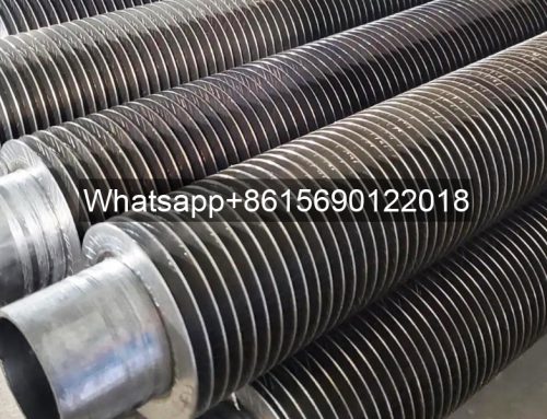
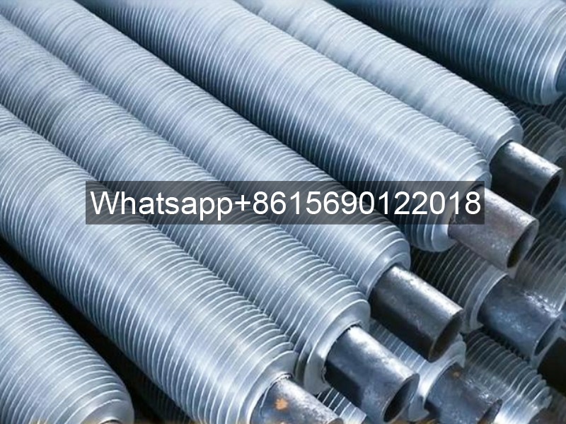
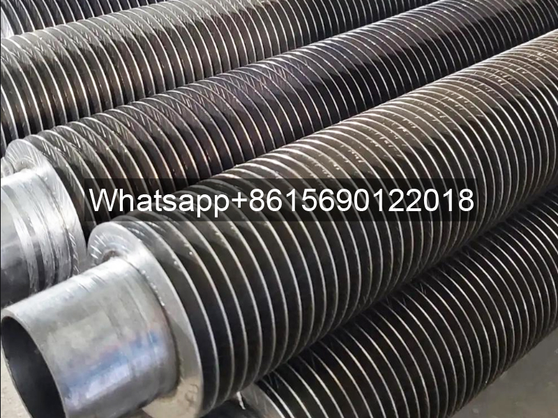
The structural characteristics of the finned tube include many fins processed on its surface, which significantly increase the heat transfer area, thereby improving the heat transfer efficiency and heat dissipation effect.
In addition, the shape, size and arrangement of the fins will also affect the heat transfer effect. The presence of fins greatly increases the heat transfer area, thereby improving the heat transfer efficiency and heat dissipation effect. At the same time, the arrangement of the fins can also guide the flow of the fluid and enhance the effect of convection heat transfer.
Finned tubes have a wide range of application scenarios, including industrial production, HVAC, automotive engineering and other fields. In industrial production, finned tube heat exchangers can transfer heat from high-temperature fluid to low-temperature fluid to achieve energy recovery and utilization, thereby improving energy utilization efficiency and reducing energy consumption.
In HVAC, finned tubes are used in evaporators and condensers to adjust indoor temperature through convection heat exchange between air and fins. In automotive engineering, finned tubes are used in engine cooling systems to help dissipate the heat generated by the engine and ensure the normal operation of the engine.
In heat exchangers composed of ordinary round tubes (light tubes), in many cases, the heat transfer coefficients of the fluid outside the tube and the fluid inside the tube to the tube wall are different. The so-called heat transfer coefficient refers to the heat transfer per unit heat exchange area and unit temperature difference (temperature difference between the fluid and the wall), which represents the size of the heat transfer capacity between the fluid and the wall.
For example:
The heat transfer coefficient of water condensing on the wall is: 10000-20000 w/(m2.℃)
The heat transfer coefficient of water boiling on the wall is: 5000—-10000 w/(m2.℃)
The heat transfer coefficient of water flowing through the wall is about: 2000—10000 w/(m2.℃)
The heat transfer coefficient of air or flue gas flowing through the wall is: 20—80 w/(m2.℃)
The heat transfer coefficient of air natural convection is only: 5—10 w/(m2.℃)
It can be seen that the difference in heat transfer capacity between fluid and wall is very large.
Next, imagine an actual heat exchange situation: inside the round tube is flowing water, whose heat transfer coefficient is 5000 (w/(m2.℃)), while outside the tube is flowing flue gas, whose heat transfer coefficient is only 50 (w/(m2.℃)), which is 100 times different. When heat is transferred from inside the tube to outside the tube, or from outside the tube to inside the tube, where does the “bottleneck” or “large resistance” of the heat transfer process occur? Of course, it is the flue gas side outside the tube, because the heat transfer coefficient, that is, the heat transfer capacity, of the flue gas side is low, which limits the increase in heat transfer.
Here, let’s take an example of series resistance: in a series circuit composed of multiple resistors, if one of the resistors is much larger than the other resistors, then this resistor will constitute the “bottleneck” of the current. Only by reducing this large resistor can the current flowing through the series circuit be effectively increased. The same is true for the above heat transfer process.
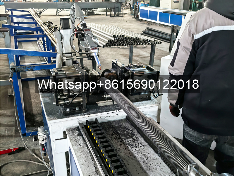
How can we improve the heat transfer of round tubes?
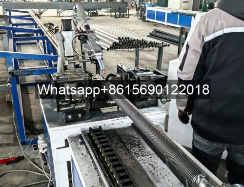
One method is to use an extended surface on the outer surface of the tube, that is, on the flue gas side, that is, to make a finned tube. Assuming that the actual heat transfer area of the finned tube is several times the original surface area of the light tube, although the heat transfer coefficient of the flue gas is still very low, the heat transfer effect reflected on the surface area of the light tube will be greatly increased, thereby enhancing the entire heat transfer process. In the case of total heat transfer, the metal consumption of the equipment is reduced and the economy is improved.

