
SPIRAL CRIMPED FIN TUBE TECHNICAL SPECIFICATION
1. Manufacturing Process
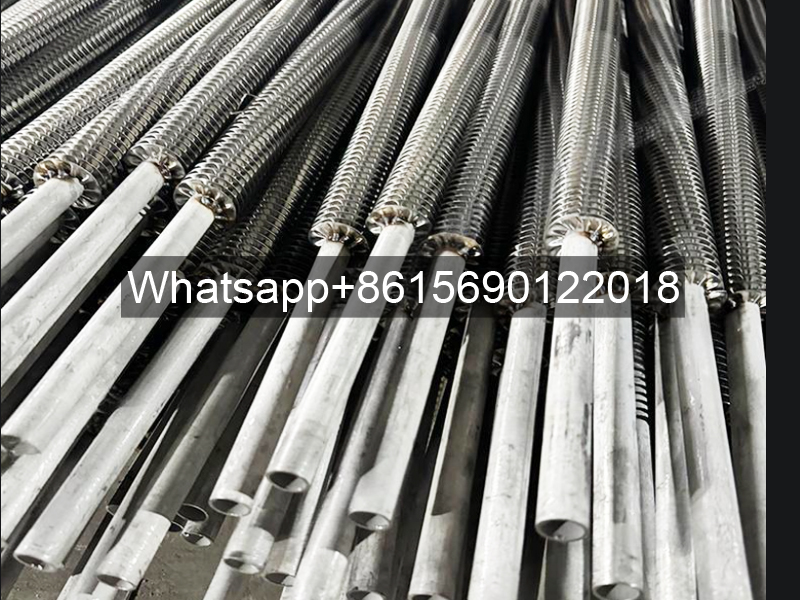
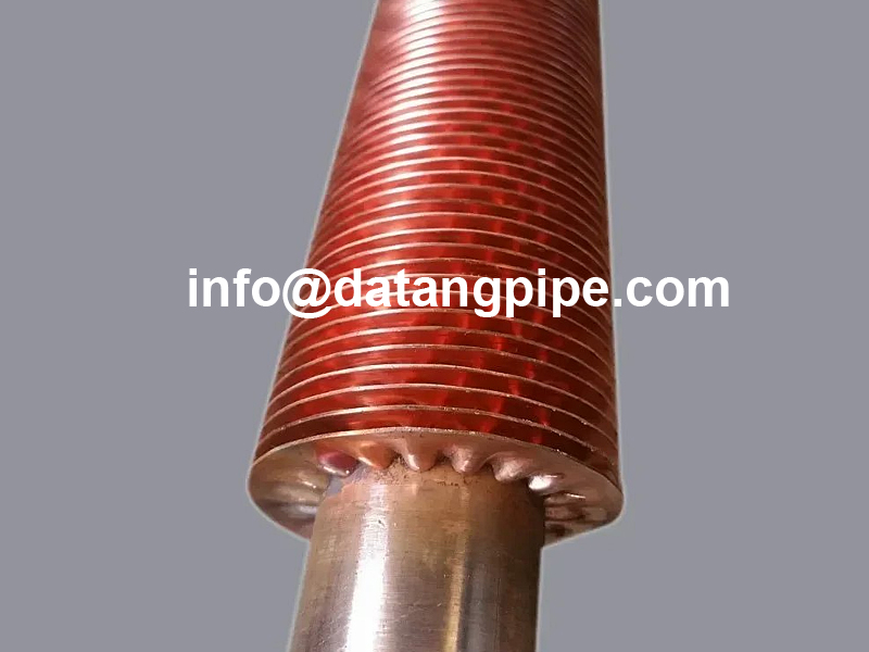
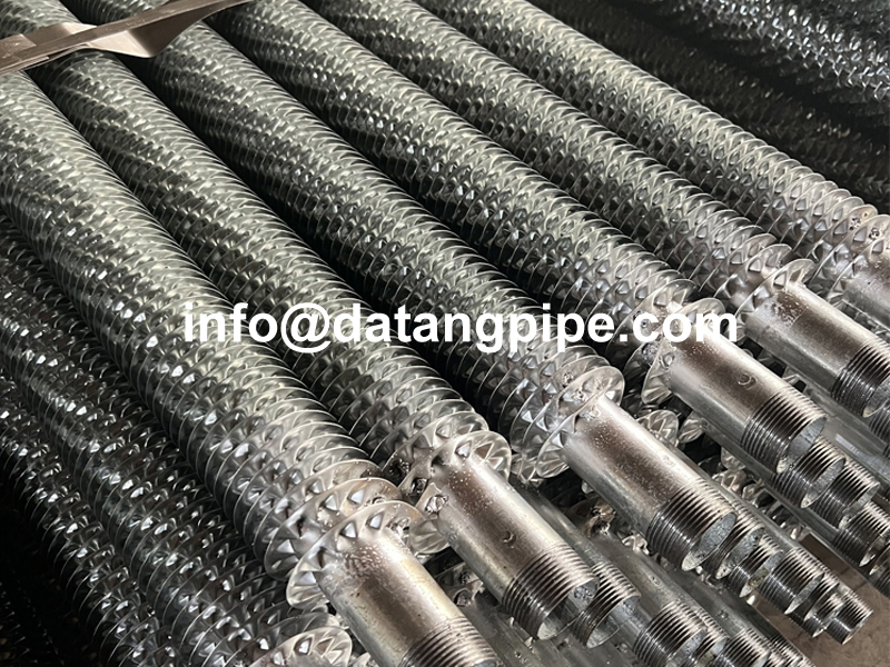
The spiral crimped fin tube production involves three key stages:
- Base Tube Preparation: Seamless/carbon steel tubes are precision-cut to required lengths (typical tolerance ±0.5mm)
- Fin Formation:
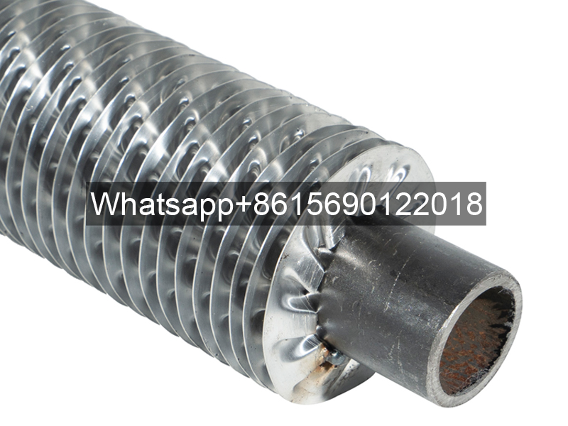
- Spiral fins are cold-formed onto tubes using specialized crimping machines (rotation speed 50-200 RPM)
- Fin pitch ranges from 2.5-12.7mm with height 6.5-16mm
- Crimping angle maintained at 30°-45° for optimal heat transfer
- Fin Bonding:
- Mechanical bonding through pressure up to 3.5 tons
- Optional brazing/soldering for high-pressure applications
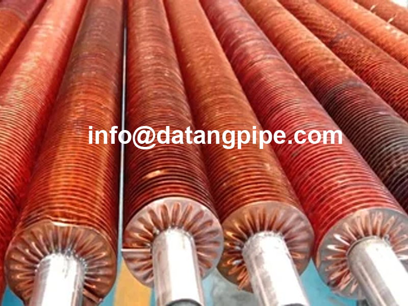
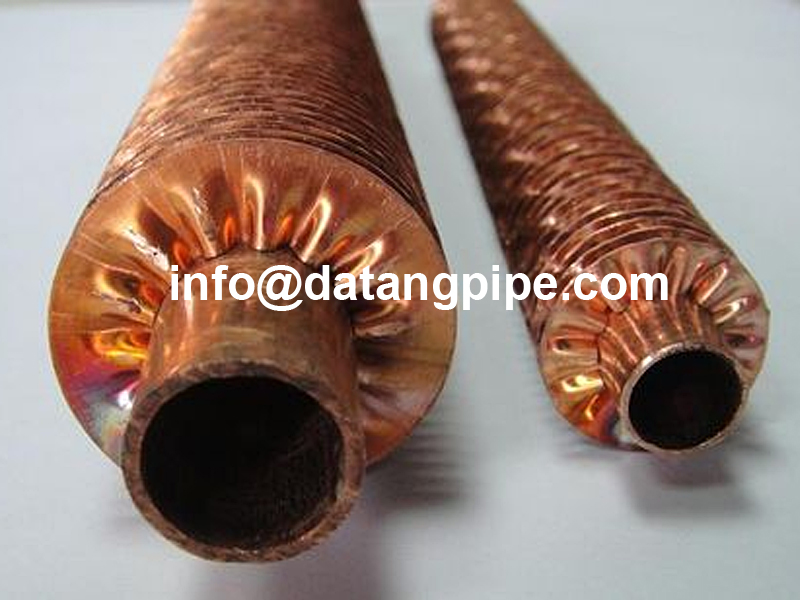
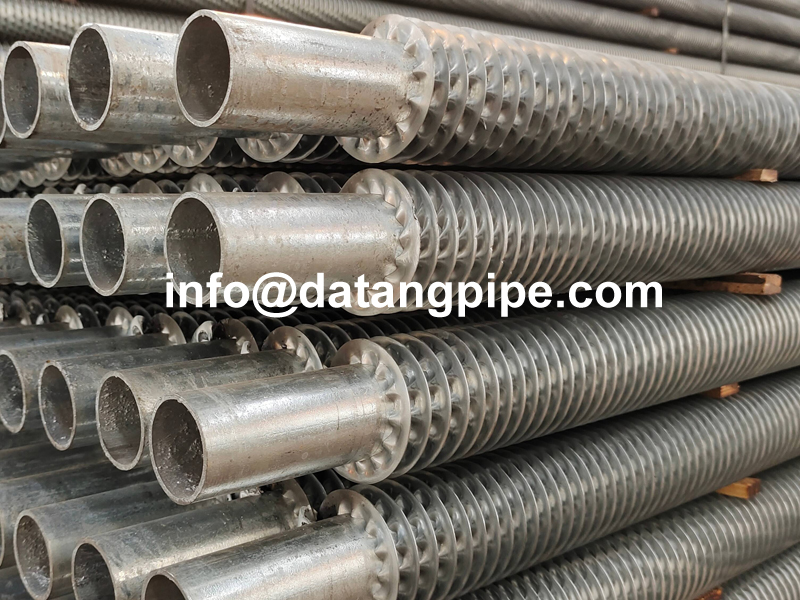
2. Material Options
ComponentAvailable MaterialsTemperature RangeBase TubeCarbon steel (ASTM A179), Stainless (304/316), Copper (C12200)-40°C to 650°CFinsAluminium (6063), Copper (C11000), Carbon steel-200°C to 580°C
3. Technical Specifications
- Standard Sizes:
- OD: 12.7mm – 50.8mm (0.5″ – 2″)
- Length: Up to 12m (custom lengths available)
- Fin thickness: 0.3mm – 1.2mm
- Performance Metrics:
- Heat transfer coefficient: 35-60 W/m²K
- Pressure rating: Up to 4.0MPa (with brazed fins)
- Surface area expansion ratio: 5:1 to 12:1
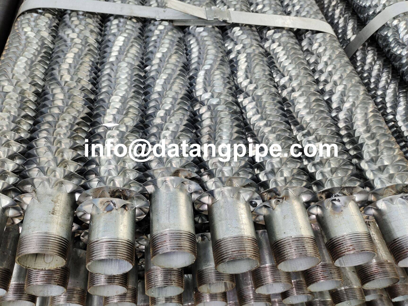
4. Industrial Applications
- Power Generation:
- Boiler economizers (coal-fired plants)
- HRSG (Heat Recovery Steam Generators)
- Process Industries:
- Oil refinery heat exchangers
- Chemical reactor cooling systems
- LNG vaporizers
- HVACR Systems:
- Industrial chillers
- Heat pump evaporators
- District heating networks
- Specialty Applications:
- Marine engine cooling
- Waste heat recovery units
- Solar thermal collectors
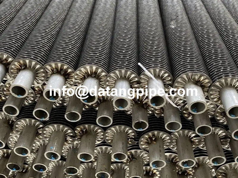
Spiral Crimped Fin Tube Installation Manual
Pre-Installation Preparation
-
Material Verification
- Confirm base tube material markings (ASTM A179/A214 carbon steel, 304/316 stainless steel, or copper alloy) match design specifications.
- Measure fin parameters:
- Fin height tolerance ≤ ±0.2mm
- Spiral angle deviation ≤ ±1.5°
- Fin pitch error ≤ ±0.3mm
-
Surface Treatment
- Clean internal tubes using compressed air (0.6MPa pressure).
- Apply anti-oxidation coating (recommend PTFE-based coating) for aluminum fins.
Mechanical Installation Procedure
1. Support System Installation
| Parameter | Requirement |
|---|---|
| Horizontal support spacing | ≤1.5m (carbon steel tubes) / ≤2m (stainless steel tubes) |
| Vertical tolerance | ≤2mm/m |
| Vibration-sensitive areas | Install rubber damping pads (hardness ≥70 Shore A) |
2. Tube Bundle Connection
-
Flange Connection:
- Bolt preload control:
- M12 bolts: 35-40Nm
- M16 bolts: 70-80Nm
- Use graphite metal-wound gaskets as priority.
- Bolt preload control:
-
Welding Connection:
Welding Type Application TIG Welding Stainless steel/copper alloy tubes MIG Welding Carbon steel tubes (argon purging required) Post-weld Eddy Current Testing (ECT) mandatory for joint integrity verification.
3. Fin Protection Measures
- Installation deformation control:
- Radial compression ≤5% of fin height
- Axial twist angle ≤3°
- For corrosive environments:
- Apply epoxy protective coating (dry film thickness ≥150μm).
System Commissioning Protocol
Pressure Testing Procedure:
- Hydrostatic test: 1.5× working pressure, hold for 30 minutes (leakage rate ≤0.1%).
- Gas tightness test: 0.6MPa nitrogen with soap solution for leak detection.
Thermal Debugging Parameters:
| Phase | Temperature Gradient | Duration |
|---|---|---|
| Preheating | ≤50°C/h | 2h |
| Steady-state | Design temp. ±10°C | 4h |
| Cooling | ≤30°C/h | To ambient |
Maintenance Regulations
- Periodic Inspections:
- Monthly visual inspection of fin fouling (permissible dust accumulation ≤1mm).
- Annual ultrasonic thickness testing (replace if wall loss ≥10%).
- Chemical Cleaning:
- Acidic solution pH control:
- Carbon steel: 4.5-5.5
- Stainless steel: 2.8-3.2.
- Acidic solution pH control:
This manual complies with ASME B31.1 Power Piping Code and applies to heat exchange systems with working pressure ≤10MPa.
Annotations marked with [ ] refer to relevant clauses in international engineering standards.
Key Technical Clarifications:
- Fin Height Tolerance: Critical for maintaining uniform airflow and heat transfer efficiency.
- Welding Gas Protection: Argon shielding prevents oxidation in carbon steel tube welding.
- Epoxy Coating Thickness: 150μm ensures corrosion resistance in pH 3-11 environments.