
Project Description
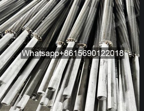
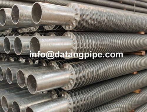
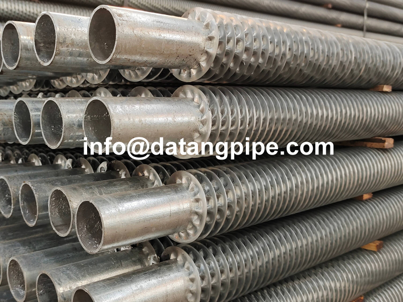
Crimped Fin Tube/Spiral Tension Wound Fin Tube
- Leave Your Message
Crimped Fin Tube/Spiral Tension Wound Fin Tube:
| Sr. No | Particulars | Range |
|---|---|---|
| 1 | Base Tube Material | Stainless Steel, Carbon Steel, Alloy Steel, Titanium, Copper, Duplex Stainless Steel, and Inconel etc. (all material in the theoretical limit) |
| 2 | Base Tube Outside Diameter | 15.88 mm to 219.00 mm OD (⅜” NB pipe to 8” NB pm) |
| 3 | Base Tube Thickness | 1.00 mm And Above |
| 4 | Base Tube Length | 500 mm Min To 15000 mm |
| 5 | Fin Material | Aluminum, Copper, Stainless Steel, Carbon Steel. |
| 6 | Fin Thickness | 0.15mm, 2.00mm |
| 7 | Fin Density | 118 FPM (3 FPI) to 433 FPM (11 FPI) |
| 8 | Fin Height | 6 mm to 25.40 mm |
| 9 | Bare Ends | As per Client Requirement |
| 10 | Manufacturing Capacity | 4,00,000 Meter Per Annum |
We can supply material on an urgent delivery basis because of large stock and relations with raw material suppliers. We use only Prime Quality base tube and Fin Material.
The Crimped Fin Tubes (Spiral Tension Wound Fin Tube) can be supplied with EN 10204 EN 3.1 and EN 3.2 certifications. We can provide Third Party Inspection from any reputed inspection agency.
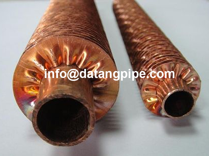
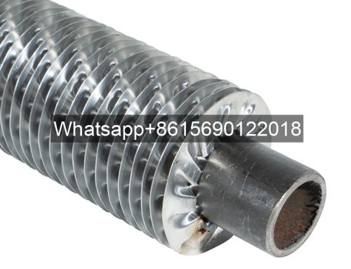
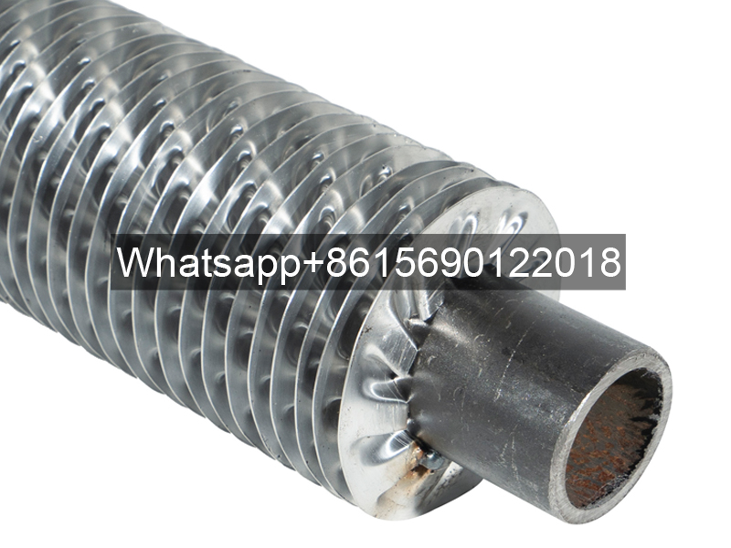
CRIMPED FIN TUBE CROSS SECTION (SPIRAL TENSION WOUND FIN TUBE CROSS SECTION)

Crimped Fin Tube (Spiral Tension wound Fin Tube):
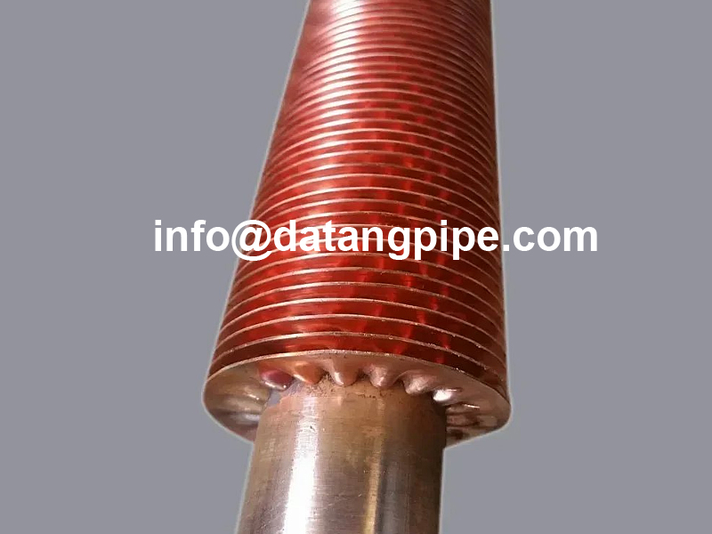
The Crimped fin tubes also known as spirally tension wound finned tubes is a very widely used finned Tube type for a various number of applications.
As the name suggests the manufacturing of Crimped Finned Tube (Spiral Tension wound Fin Tube) is done by Tension winding of fin material on the base tube. The base tip of the fin strip is pre formed on a set of performing rollers.
This pre forming allows for a wider base and hence contact area is increased. It also enables more turbulence for the air flowing over the finned tube thereby increasing heat transfer efficiency. The ends of Fins are tag welded to secure its bond on the base.
This finning takes place on dedicated specially designed finning machines with auto feed mechanism. This process allows a very long length of tubes to be finned.
It finds application in various industries ranging from driers, radiators, heaters etc and are used in many industries like food, chemical, Oil Cooling etc.
Properties of Crimped Fin Tubes (Spiral Tension Wound Fin Tube):-
- Manufacturing Process:- Spirally Tension Wound (Crimped Fin Tube)
- Fin To Tube Bond:- Moderate
- Heat Transfer Efficiency:- Good
- Mechanical Resistance:- Very Good
- Corrosion Protection:- Moderate to very good (based on material properties of Fins & Tube)
- Temperature Range:- Upto Maximum 120 Deg C
Crimped Fin Tube, Crimped Type Fin Tube
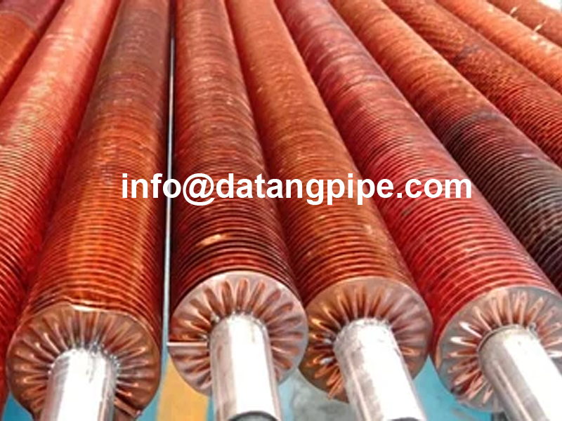
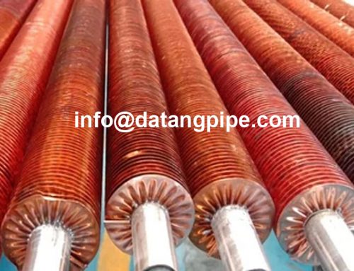
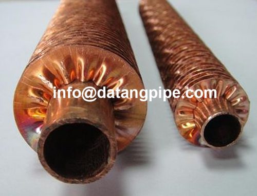
Crimped Finned Tube, also known as Cold Raised Finned Tube, is to spirally wound crimped fins on the base tube without welding, but spot welding. Root welded or fully tinned non-ferrous tubes and fins.
Crimped Fins are spirally wrapped onto the base tube, without welding, but spot welded. The steel strip can be copper, carbon steel, stainless steel. Non-ferrous tubes and fins on either root soldered or completely tinned.
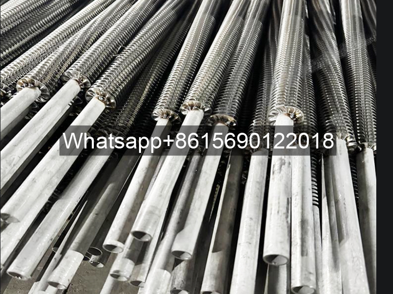
Helical Tension Wound Finned Tubes for Air Cooler Since the stainless steel is with high corrosion resistance, the stainless steel crimped fin tube can be widely used when the circumstance has a certain degree of corrosion or cleanliness, such as climatic industry, heating, drying and cooling. Usually applied in fin tube heat exchangers. Maximum working temperature is 180℃.
Crimped Fin Tubes offer a higher airside turbulence and heat transfer on account of the crimping of the fins as compared to the L Type Fin Tube.
Material Standard of crimped fin tube
Both base tube and fin can be carbon steel and stainless steel
Carbon Steel: A179, A192,SA210 Gr A1/C,A106 Gr B
Stainless Steel: TP304/TP304L , TP316 / TP316L
Finned Tube Heaters Copper
Both base tube and fin can be copper, carbon steel and stainless steel
Carbon Steel: A179, A192,SA210 Gr A1/C,A106 Gr B
Stainless Steel: TP304/TP304L , TP316 / TP316L
Specification of crimped fin tube
Base Tube OD: 15.88-51mm
Fin Pitch: 3.5-10mm
Fin Height: maximum 16mm
Fin Thickness: 0.2-0.4mm
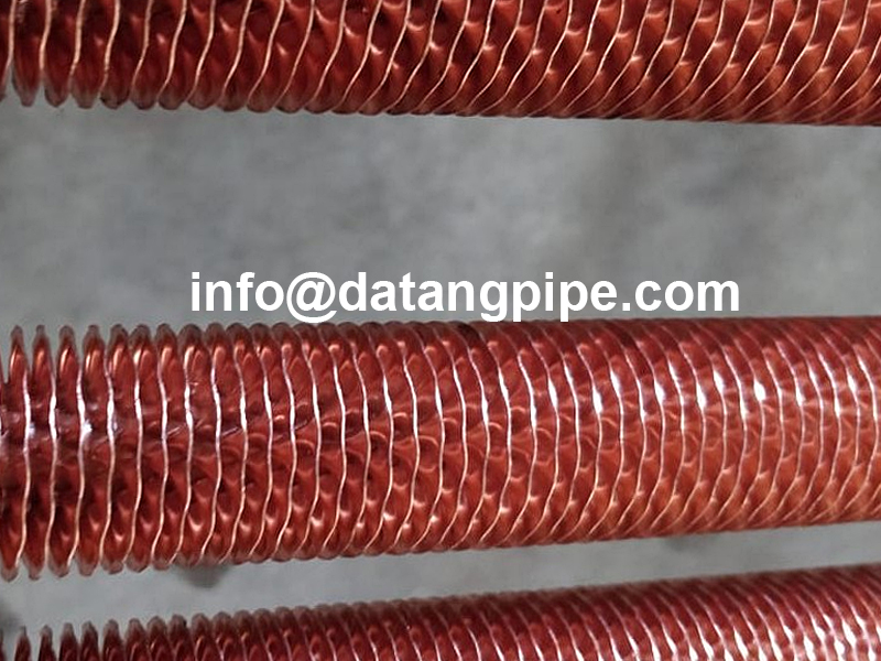
Features of crimped fin tube
Fins and tubes are connected tightly
Uniform pitch, small fold, no ash accumulation
Small thermal contact resistance, high heat transfer capability
Maximum working temperature: 120°C
Helically tension wound finned tubes for air cooler
Helically Tension Wound Finned Tubes For Air Cooler
Since the stainless steel is with high corrosion resistance, the stainless steel crimped fin tube can be widely used when the circumstance has a certain degree of corrosion or cleanliness, such as climatic industry, heating, drying and cooling. Usually applied in fin tube heat exchangers.
Maximum working temperature is 180℃.
Crimped Fin Tube (Spiral Tension wound Fin Tube):
The Crimped fin tubes also known as spirally tension wound finned tubes is a very widely used finned Tube type for a various number of applications.
As the name suggests the manufacturing of Crimped Finned Tube (Spiral Tension wound Fin Tube) is done by Tension winding of fin material on the base tube. The base tip of the fin strip is pre formed on a set of performing rollers.
Fin Tube Advantages
Transferring heat from a hot fluid into a colder fluid through a tube wall is the reason many of us use finned tubes.
But you may ask, what is the major advantage of using a finned tube? Why can’t you just use a regular tube to make this transfer? Well you can but the rate will be much slower.
By not using a finned tube the outside surface area is not significantly greater than the inside surface area. Because of that, the fluid with the lowest heat transfer coefficient will dictate the overall heat transfer rate. When the heat transfer coefficient of the fluid inside the tube is several times larger than that of the fluid outside the tube the overall heat transfer rate can be greatly improved by increasing the outside surface area of the tube.
Finned tubes increase outside the surface area. By having a finned tube in place, it increases the overall heat transfer rate. This then decreases the total number of tubes required for a given application which then also reduces overall equipment size and can in the long-run decrease the cost of the project. In many application cases, one finned tube replaces six or more bare tubes at less than 1/3 the cost and 1/4 the volume.
For applications that involve the transfer of heat from a hot fluid to a colder fluid through a tube wall, fin tubes are used. Usually, for an air heat exchanger, where one of the fluids is air or some other gas, the air side heat transfer coefficient will be much lower, so additional heat transfer surface area or a fin tube exchanger is very useful. The overall pattern flow of a finned tube exchanger is often crossflow, however, it can also be parallel flow or counterflow.
Fins are used to increase the effective surface area of heat exchanger tubing. Furthermore, finned tubes are used when the heat transfer coefficient on the outside of the tubes is appreciably lower than that on the inside. In other words, heat transferred from liquid to gas, vapor to gas, such as steam to air heat exchanger, and thermic fluid to air heat exchanger.
The rate at which such heat transfer can occur depends on three factors – [1] the temperature difference between the two fluids; [2] the heat transfer coefficient between each of the fluids and the tube wall; and [3] the surface area to which each fluid is exposed.