
What are Helical Finned Tubes?
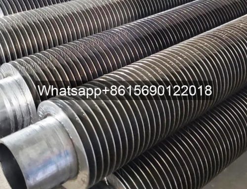
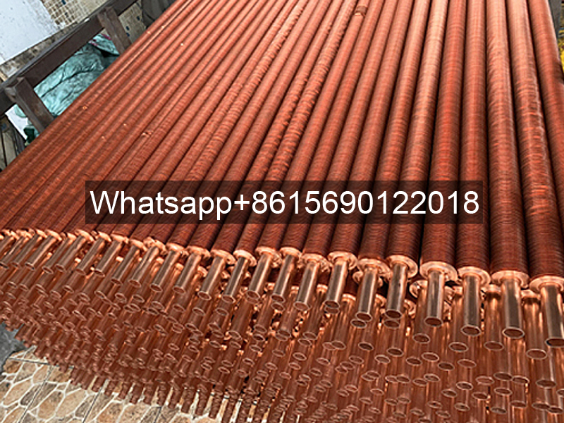
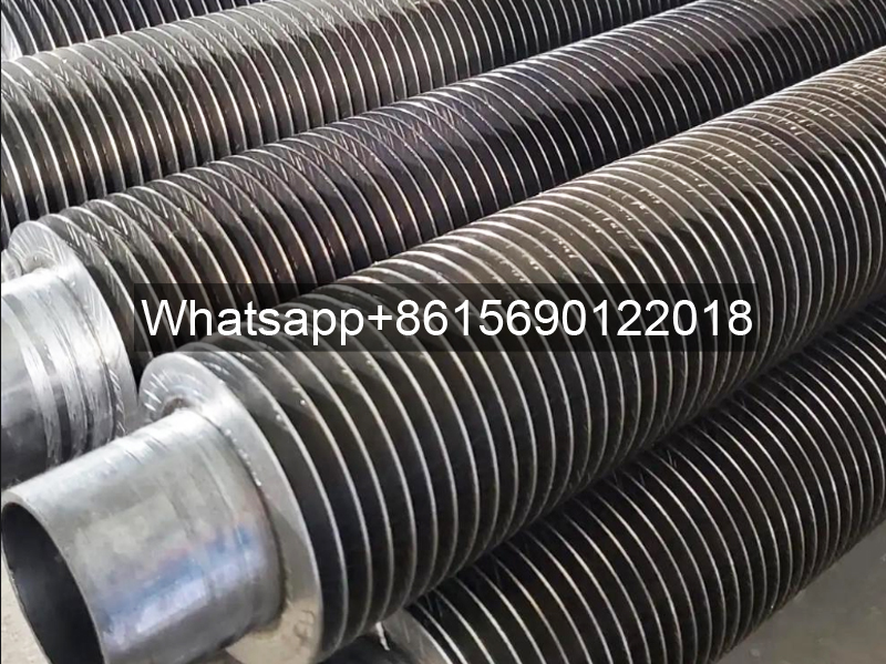
Helical finned tubes are heat exchange elements that utilize spiral fins to enhance heat transfer. They are energy-saving heat transfer components for equipment such as boilers and pressure vessels. Their heat transfer area can reach several to dozens of times that of plain tubes. Manufacturing processes include high-frequency resistance welding, brazing, and roll forming. Integral helical finned tubes utilize a hot rolling process to integrate the fins and base tube, extending their service life by more than three times.

Helical Finned Tube-Helical Fin Tube
These components reduce flow resistance and metal consumption. Their weld-free design improves pressure bearing capacity and wear resistance, effectively addressing the dust accumulation and weld cracking issues associated with traditional finned tubes. Applications include boiler economizers, air preheaters, and gas-fired boilers.
Helical finned tubes are widely used for heat recovery in boiler economizers, air preheaters, and waste heat boilers, as well as in heat exchange equipment in various fields, including the chemical industry and pressure vessels. Their use in boilers is expanding, with units ranging from small to large in capacity.
Advantages of using finned tubes:
1) Increased heat transfer area within the effective space improves heat transfer efficiency.
2) Reduced space occupied by the heat transfer surface, resulting in a smaller volume, making it particularly suitable for packaged boilers.
3) Reduced equipment costs and improved safety.
4) Reduced operating costs due to reduced water-side pressure drop.
5) Increased finned tube rigidity improves seismic resistance.
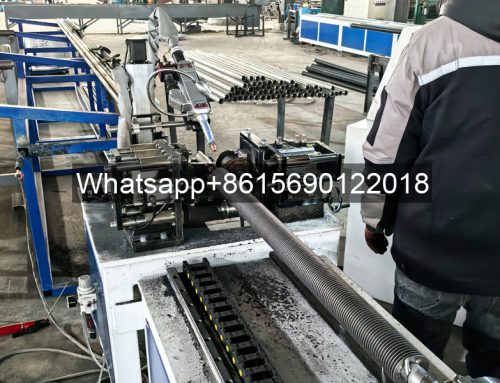
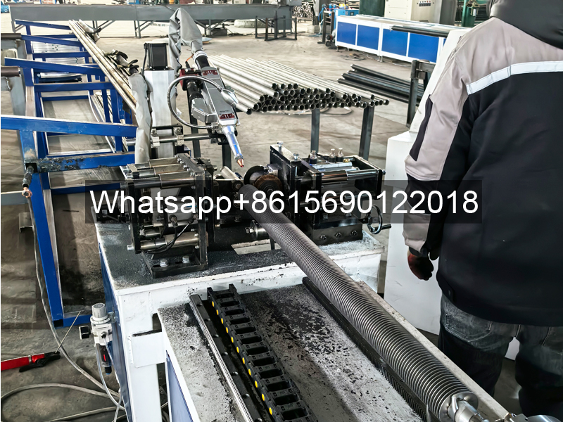
Helical Finned Tube Manufacturing Methods
Helical finned tubes can be manufactured using a variety of methods. The following are the main methods for manufacturing finned tubes used in heat exchange equipment such as boilers and pressure vessels:
High-Frequency Resistance Welded Helical Finned Tubes
High-Frequency Resistance Welded Helical Finned Tubes involve introducing a high-power, high-frequency current into the welded parts. The resistance heat generated by the current passing through the welded joint and the adjacent areas causes the weld surface to reach a molten or semi-molten plastic state. Appropriate pressure is then applied to the weld surface to complete the finned tube welding.
Brazed Helical Fin Tubes
Brazed helical fin tubes are made by filling the space between the welded parts with a brazing filler metal with a lower melting point than the welded parts. The brazing temperature is then raised. While the welded parts remain unchanged, the brazing filler metal melts and wets the welded parts, forming a brazed joint through diffusion at the welded parts’ contact points.
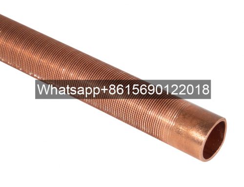
Integrated Helical Fin Tubes
Integrated helical fin tubes are formed in one step by extruding and rolling a thick-walled tube (a blank) under continuous medium-frequency heating. A domestic company has developed a patent for both the integrated spiral fin tube and its in-house integrated fin tube manufacturing equipment.
Helical Fin Tube Performance
Helical fin tubes primarily utilize the three manufacturing methods described above. For ease of analysis and comparison, spiral fin tubes are divided into welded fin tubes (high-frequency welding, brazing) and integral helical fin tubes for comparison.
Welding penetration, also known as fusion rate, is a performance metric that assesses the width and total length of the fin weld. The weld fusion rate across the width of the steel strip must be no less than 80%. While the longitudinal direction is not specified, it is understood that a weld fusion rate of no less than 80% along the entire fin length is acceptable.
The length of any local lack of fusion in the weld must not exceed the tube diameter and no more than 50mm. The number of lack of fusion points must not exceed two per meter; otherwise, repair welding is required.
The total actual weld length must be no less than 90% of the total fin length, and the average weld width must be no less than 80% of the fin width.
The actual weld penetration rate for high-frequency resistance welded spiral fin tubes can reach 90%-95%. The weld penetration rate for brazed spiral fin tubes is slightly higher than that of high-frequency welding, but the weld penetration rate is difficult to check.
As the name suggests, the fins of integral spiral fin tubes are formed from the tube. Therefore, there is no fin welding issue and weld penetration inspection is not required.
Weld Tensile Strength
The tensile strength of welded specimens must be no less than 196 MPa. HG/T 3181-92 does not specify this.
For high-frequency resistance welded helical fin tubes, manufacturers have achieved weld tensile strengths exceeding 200 MPa, or even exceeding 300 MPa. The weld tensile strength of brazed spiral fin tubes can also generally meet this requirement.
The fins of integral helical fin tubes are extruded and rolled from the base tube, so there is no weld tensile strength issue. The strength of the fin-to-tube connection is equivalent to, or even slightly higher than, the tensile strength of the corresponding tube material.
Post-Weld Heat Treatment
The heat-affected zone (HAZ) of high-frequency resistance welded spiral finned tubes is very small. International standards specify a HAZ <0.8mm, while some domestic manufacturers’ products actually measure less than 0.5mm. Alloy steel finned tubes should undergo stress-relief heat treatment after welding.
The production process of integral spiral finned tubes is essentially a re-extrusion and rolling process of the original thick-walled billet tube at high temperatures. After high-temperature extrusion and rolling, stress-relief heat treatment is not required.
Heat Transfer Performance
The heat transfer performance of high-frequency resistance welded and brazed spiral finned tubes is at least four times higher than that of plain tubes.
Finned tubes with serrated edges offer even better heat transfer than those with full fins. However, it should be noted that the weld penetration rate between the fin and tube is not 100%, and the standard specifies only 80% or higher. Unfused areas create thermal resistance, which can affect heat transfer.
The 100% contact between the fins and the mother tube of the integral helical fin tube, coupled with the small R transition between the fin root and the mother tube during molding, not only increases the fin rigidity and pressure-bearing capacity, but also facilitates heat transfer. Its heat transfer efficiency is at least 5-6 times higher than that of plain tubes, significantly surpassing that of high-frequency resistance welded or brazed helical fin tubes.
Service Life
High-frequency resistance welded helical fin tubes weld by simultaneously applying pressure while melting the two metal surfaces at contact. This results in a high weld rate and weld metal corrosion resistance that is more than double that of brazing, significantly extending the service life of the fin tube. However, due to weak welds, weld cracking can easily occur over long-term use, causing the fins to separate from the tube, compromising heat transfer efficiency and necessitating replacement of the fin tube.
Integral helical fin tubes eliminate the fin welding issues, eliminating the need to worry about fin corrosion or cracking, and their heat transfer efficiency remains unchanged.
The increased surface hardness of integral helical fin tubes enhances their wear resistance. Furthermore, the structural features of the fin root facilitate heat transfer. Therefore, the service life of integral spiral fin tubes is equivalent to the lifespan of the original fin material, at least two to three times that of high-frequency welded or brazed spiral fin tubes.
Economical
Brazed helical fin tubes require a third material—the brazing filler metal. During brazing, the fins undergo a series of steps, including cold winding, solder spraying, and sintering, resulting in higher manufacturing costs. High-frequency resistance welded spiral fin tubes, on the other hand, do not require a third material; the fins are formed in a single winding process, resulting in a relatively lower cost. The winding start and end of high-frequency resistance welded or brazed spiral fin tubes should be secured by hand welding before welding.
Integrated helical fin tubes are made from thick-walled tubes through extrusion and rolling. This eliminates the need for a second material, eliminating the multiple steps required for high-frequency resistance welded fins, such as winding and welding. This results in higher production efficiency and lower costs. The fin root of the integral spiral fin tube has a small R smooth transition to facilitate heat transfer.
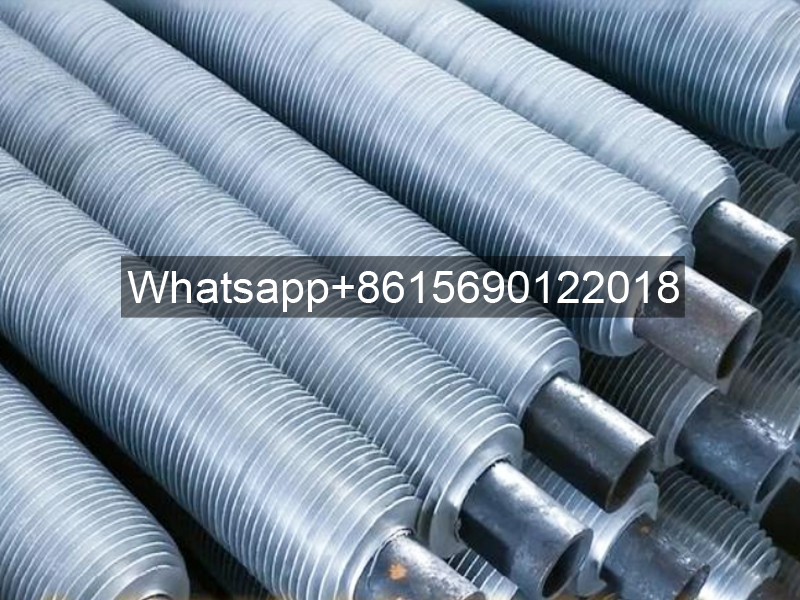
Technical Advantages of Helical Fin Tubes
Helical fin tubes are commonly used in wound, high-frequency welded, or brazed types. Integral spiral fin tubes, with their long service life, stable heat transfer performance, and significant energy savings, have become the successor to these three types.
Advantages of Helical Fin Tubes
1. Long service life, over three times that of wound and welded finned steel tubes.
2. The fin roots are curved and cut into the tube, resulting in a smooth fin surface, completely eliminating the dust accumulation, clogging, and slagging that can occur with other fin tubes due to the uneven folding of the fin roots.
3. The hot rolling process improves the metal structure’s density, yield strength, tensile strength, and wear resistance.
4. Because the fins are integrated with the tube and arranged in a spiral band, the pressure-bearing capacity of integral spiral fin steel tubes is over three times that of seamless steel tubes of the same wall thickness and inner diameter.
5. Wear resistance solves the problem of severe wear on the convection heating surfaces of coal-fired boilers caused by high wind speeds and high ash concentrations.
6. The fins and tubes are integrated, completely eliminating the contact thermal resistance that cannot be overcome in other finned steel tubes due to the two-piece structure of the fins and tubes. The fins also have a trapezoidal longitudinal cross-section, maximizing the fin heat transfer efficiency.
7. The use of integral spiral fins for extended surface heat transfer means that, under equivalent operating conditions, the heat transfer coefficient of the tube bundle is 3.5-5.5 times that of seamless steel tubes of the same wall thickness and inner diameter, and twice that of welded spiral fin steel tubes of the same specification.
8. The integrated fin and tube structure eliminates the unstable heat transfer performance caused by fin loosening or detachment that can occur with other finned steel tubes.
Fin Structural Parameter Design
When gas turbine exhaust transfers heat to the steam inside the tubes through spirally finned tubes, while the spiral fins enhance the heat transfer capacity of the heating surface, they also expose the outer fins to a harsh, high-temperature environment. This often results in high temperatures on the outer fins, potentially exceeding the material’s allowable temperature resistance, causing them to burn.
For waste heat boilers, the high-pressure superheater and reheater heating surfaces experience high temperatures due to both the flue gas outside the tubes and the working fluid inside. If the fin height is not designed appropriately, the temperature at the outermost ends of the spiral fins (commonly known as the fin tip temperature) may exceed the allowable temperature of the fin material, leading to fin burnout and impacting the operational reliability of the waste heat boiler.
Structural Design of Finned Tube Bundles
For most finned tube bundles in actual operation, the heat transfer characteristics of spirally finned tube bundles are still dependent on the fin welding method and weld penetration rate. Unavoidable differences exist between domestic and international fin tube welding processes.
Helical Fin Tube Manufacturing Process
The enhanced heat transfer effect of serrated helical fin tubes has been recognized. However, the development of this type of fin tube has been limited to some extent by complex manufacturing processes, high costs, and complex processing equipment. Therefore, while optimizing the structure of the finned tube bundle, it is also important to focus on researching the processing technology to simplify manufacturing technology, minimize costs, and maximize profits.
Determining the Heat Transfer Coefficient
The fin temperature distribution on a helical finned tube bundle is closely related to the heat transfer characteristics of each tube row, and the fin temperature distribution directly affects the reliability of the finned tube bundle.
Wear Problems
In coal-fired boilers, the finned tube bundle is subject to wear from ash ingress. The amount of wear is proportional to the cube of the flue gas flow rate. Therefore, selecting the appropriate flue gas flow rate is extremely important for boiler operation safety.

