
Project Description
- Product Name: Integral Low Finned U-Bend Tube | Integral Low Fin Tubing
- Leave Your Message
What is Integral Low Finned U-Bend Tube?
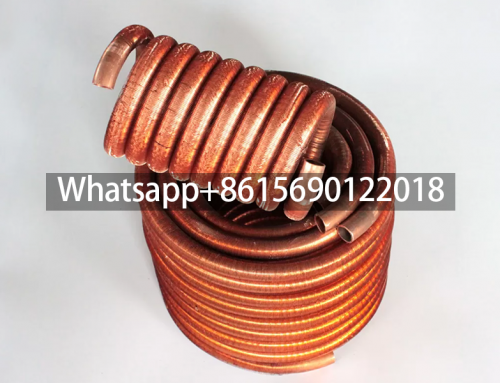
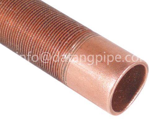
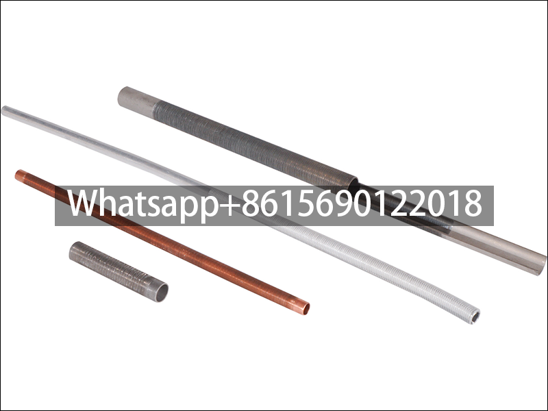
U-bend low finned tube is a heat exchange element with continuous spiral fins formed on the surface of the base tube by machining, and is commonly used in equipment such as air conditioning condensers. Its core structural features are as follows:
Integral Low Finned U-Bend Tube Structural Features
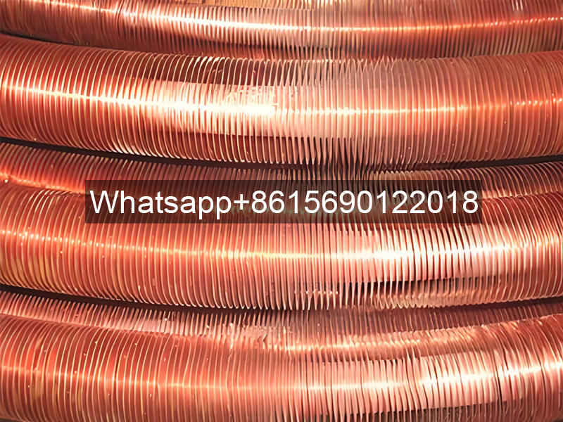
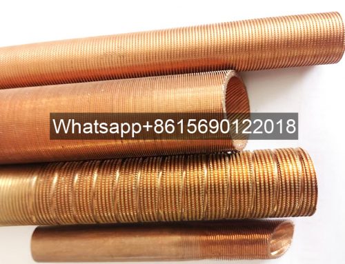
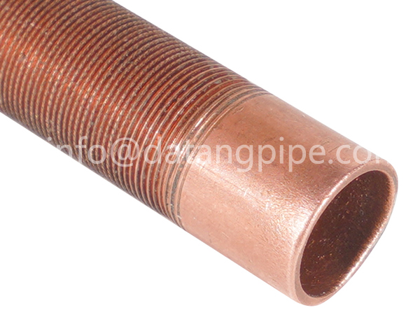
Integral Low Finned U-Bend Tube adopts a U-shaped design. The base tube is mostly a seamless steel tube, and continuous spiral fins are formed on the surface by machining. These fins have a specific height, fin pitch and thickness, and improve heat transfer efficiency by increasing the surface area.

Low Finned U-Bend Tube Application Scenarios
It is mainly used in the condenser of the air conditioning system and has become a key component with its high heat transfer efficiency. Compared with ordinary finned tubes, the U-shaped design may further optimize space utilization and fluid path.
U-bend low-fin tube processing technology
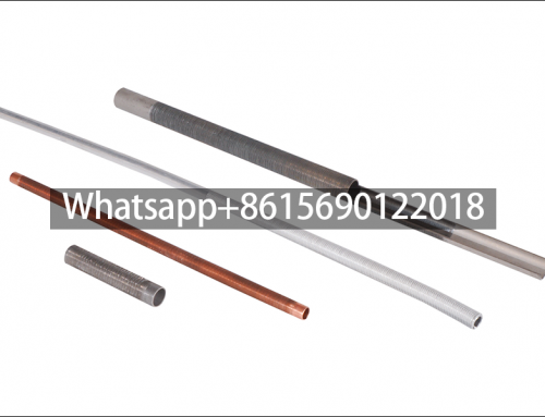
The fin structure is formed outside the light tube by mechanical processing (such as turning or rolling). The process is highly controllable and can be customized to produce different specifications and parameters.
Here is the professional English translation of the technical specifications and application guidelines for U-Type Low-Finned Tubes:
???? I. Core Structure & Enhancement Mechanism
-
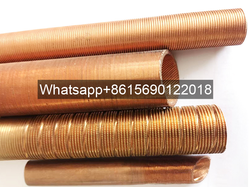
Low-Fin Design Characteristics
- Fin Ratio (β=2~3): Continuous helical fins are rolled onto the base tube surface, expanding the effective heat transfer area by 2-3× while maintaining mechanical strength.
- Anti-Fouling Self-Cleaning: Thermal expansion/contraction generates an “accordion effect” that peels off parallel scale layers, preventing cylindrical fouling (unachievable with smooth tubes).
- Secondary Heat Transfer Enhancement: Fins disrupt laminar boundary layers, intensify fluid turbulence, and increase heat transfer coefficients by >50%.
-
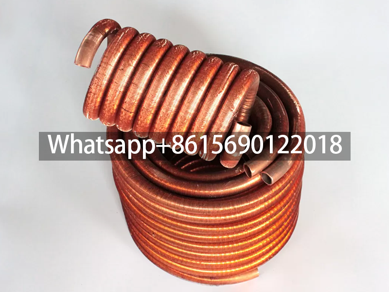
U-Bend Advantages
- The 180° semi-circular structure absorbs thermal stress, preventing weld cracks in applications with ΔT > 80°C (e.g., condensers).
- Combined with longitudinal fins, heat transfer performance increases by 30% vs. straight tubes.
⚙️ II. Key Parameters & Process Standards
| Parameter | Typical Value | Function/Risk |
|---|---|---|
| Fin Height | 1.0-2.5 mm | 2.5 mm: high air resistance |
| Fin Pitch | 1.5-2.5 mm | 2.5 mm: reduced efficiency |
| Base Tube OD | 19-38 mm (DN15-DN50) | Smaller tubes: higher flow resistance but better heat transfer |
| Bend Radius | ≥2× tube diameter | Smaller radii cause stress concentration at fin roots |
Process Essentials:
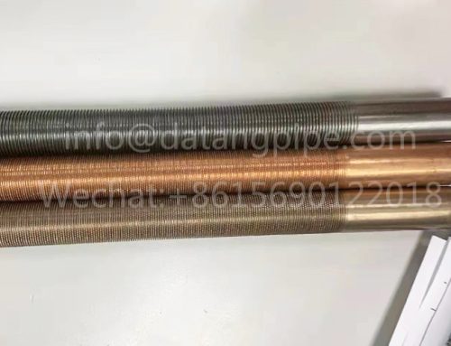
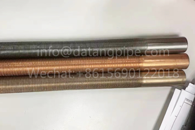
- Material: Primarily 304/316L stainless steel (corrosion-resistant); carbon steel requires zinc plating.
- Forming: Cold roll-bending (stainless steel) or hot-bending (carbon steel)—ensures integral fins with zero contact thermal resistance.
- Welding: Laser-welded fins to avoid false welding and thermal resistance.
III. Performance Comparison & Application Scenarios
-
vs. Smooth Tubes / U-Type Smooth Tubes
- Heat Transfer Efficiency: 40%-60% higher heat exchange; >20% reduction in steam consumption.
- Vibration Resistance: Fin structure raises natural frequency, reducing flow-induced vibration.
- Geothermal Heat Pumps: U-finned tubes achieve 35% higher heat exchange per borehole depth vs. smooth tubes, especially in high-flow regimes.
-
Typical Applications
- Chemical Equipment: Reactor condensers (316L for acid/alkali resistance), distillation column reboilers.
- Power Systems: Boiler flue gas waste heat recovery (fins resist ash erosion), turbine lube oil cooling.
- Data Centers: U-tube heat pipe dehumidification systems for pre-cooling fresh air and reducing AC load.
️ IV. Selection & Maintenance Guidelines
-
Design Restrictions
- Prioritize threaded tubes over finned tubes if external film coefficient < 1.5× internal coefficient.
- Fin pitch ≥3 mm required for media with solid particles to prevent clogging.
-
Operational Risks
- Cleaning Prohibition: Avoid hydrochloric acid; use citric acid circulation (concentration ≤5%).
- Welding Exclusion Zone: No welding within 50 mm of finned sections; straight tube segments required.
???? Industry Case Study
A chemical plant replaced smooth-tube condensers with DN32 stainless steel U-type low-finned tubes (fin height: 1.8 mm; pitch: 2 mm), achieving 22% lower steam consumption and annual savings of ¥1.8 million. Key success: fin-induced turbulence resolved heat exchange attenuation in high-viscosity crude oil.
Note: Selection must consider media properties (viscosity, corrosivity), flow velocity, and space constraints.
Fin tube bending equipment:
