
Project Description
Product Name: Fin Fan Cooler Heat Exchanger
- Leave Your Message
Fin Fan Cooler Heat Exchanger Manufacturer and Supplier Factory 20 Years
As a widely used heat exchanger in the industrial sector, the structural design of the fin fan cooler heat exchanger directly impacts heat exchange efficiency, energy consumption, and applicable scenarios.
Depending on the airflow organization, tube bundle layout, and auxiliary configurations, fin fan coolers can be categorized into various types, including horizontal, sloping, and vertical. Each structure offers unique performance advantages under specific operating conditions.
Horizontal Fin Fan Cooler Heat Exchanger: Efficient Heat Dissipation
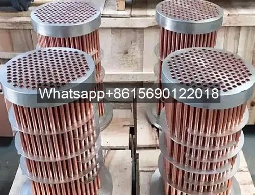
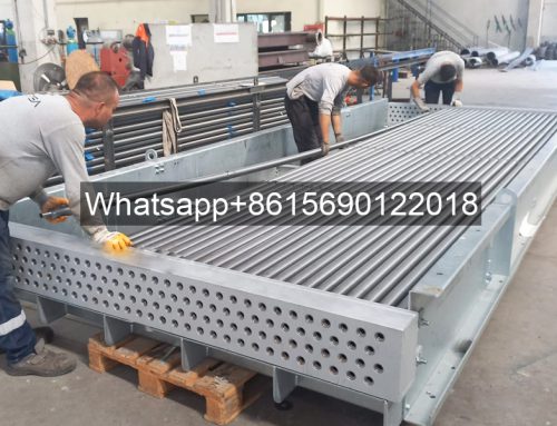
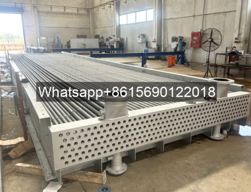
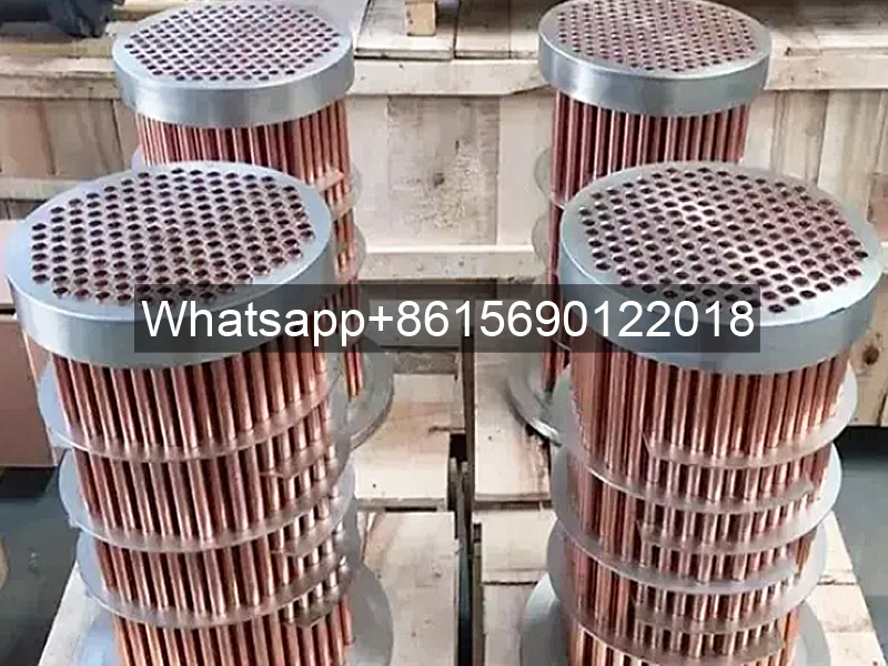
The horizontal structure is the basic form of the fin fan cooler heat exchanger. It consists of a standardized unit consisting of a tube bundle, a fan, and a frame. The tube bundle is arranged horizontally above the fan, and air flows vertically upward through the tube bundle via an axial fan, achieving heat exchange. Features of this design include:
1. Tube Bundle Configuration: Staggered embedded fin tubes or L-shaped fin tubes are used. The fin density is typically 200-250 fins/meter, and the tube center-to-center distance is controlled at 50-60mm to balance airflow resistance and heat exchange area.
2. Fan System: Equipped with an axial flow fan with a diameter of 2.4-4.5 meters, blades made of fiberglass or aluminum alloy, and a speed controlled between 200-400 rpm. Some new models are equipped with variable-frequency motors, reducing energy consumption by 15%-20% compared to traditional structures.
3. Anti-freeze Design: Horizontal Fin Fan Cooler Heat Exchangers used in cold regions incorporate steam tracing pipes, which are routed along the bottom of the tube bundle to maintain the tube wall temperature above 5°C in winter to prevent freezing of the medium.
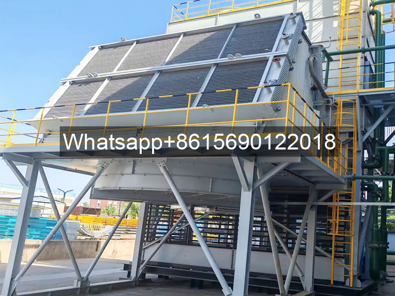
Inclined Roof Blower Fin Fan Cooler Heat Exchanger
For harsh environments such as high temperatures and high dust levels, the inclined roof design significantly improves operational reliability by altering the airflow path. Its core differences are:
1. Inclined Design: The tube bundle is angled 45-60° from the horizontal, forming a herringbone layout. This structure allows dust particles to slide down the slope under the influence of gravity. A coal chemical project application demonstrated that the inclined roof design reduced fin dust accumulation by 70% compared to horizontal designs, extending cleaning cycles from two weeks to two months.
2. Hot Air Recirculation Suppression: The unique V-shaped duct design directs hot exhaust air upward, effectively eliminating the hot air backflow problem common with horizontal designs.
3. Modular Expansion: Utilizing a modular design, each module typically has a heat exchange area of 200-300 square meters. These modules can be connected in parallel to meet heat exchange requirements of 1,000 square meters.
A refinery’s atmospheric and vacuum unit utilizes eight modules of inclined roof air coolers, with a total heat exchange area of 2,400 square meters.
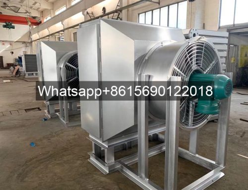
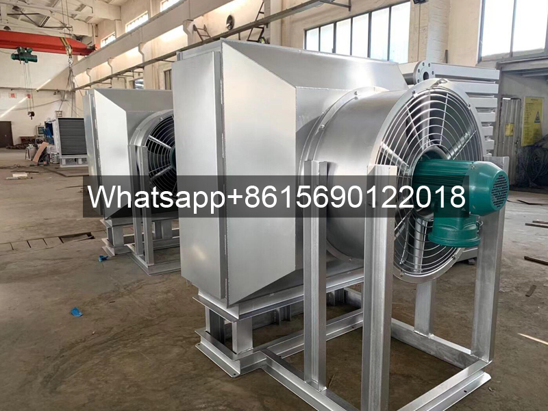
Vertical Blower Fin Fan Cooler Heat Exchanger: A solution for space-constrained applications
The vertical design achieves a compact layout by redirecting airflow. Key features include:
1. Vertical Tube Bundle Arrangement: Tube bundles are installed vertically on both sides of the frame, creating a double-sided air intake structure. This design reduces the equipment’s footprint by 40%, making it particularly suitable for space-constrained locations such as offshore platforms.
2. Wind Resistance: Utilizing a centrifugal fan and a wind deflector design, the vertical structure offers significant advantages over the horizontal design in typhoon-prone areas.
3. Maintenance Ease: The removable panel design allows individual heat exchange tubes to be replaced without lifting the tube bundle, reducing maintenance time by 50%.
Fin Fan Cooler Compound Structure
1. Horizontal-Slanted-Top Composite Structure: A horizontal tube bundle in the front section performs the primary heat exchange, while a slanted-top tube bundle in the rear section provides deep cooling. Application data from an ethylene plant shows that this structure reduces the final cooling temperature by 8-10°C.
2. Induced Draft-Forced Draft Combined Structure: An induced draft fan is added after the conventional forced draft unit to create a forced ventilation system. Although energy consumption increases by 15%, the heat transfer coefficient improves by 30%, making it suitable for cooling high-viscosity media.